


Globe valves
Globe valves
Globe valves are a popular type of pipeline fitting that is often used in various pipelines to completely stop the fluid transport process. To stop the flow of liquids with a globe valve a valve with a lead thread is usually used, which allows you to maintain any of its positions (even if you must interact with a powerful flow). Control of these pipeline fittings can be done in manual or automatic mode. Globe valves are made from cast iron, bronze or steel. Regardless of the materials used in the production of structural elements of pipeline fittings, in any case, uninterrupted and high-quality operation of the device is ensured for a long time (considering the systematic maintenance provided for in the technical specifications).

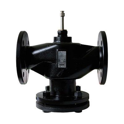
VF - flanged globe valves
The flanged globe valves series VF are used in heating, refrigeration and air-conditioning systems for the flow control of heated or chilled water for domestic and industrial applications. The valves are motorized by the AVF series electric actuators with actuating force of 1200 N (up to DN80) and 1800 N (from DN100 up to DN200). Make sure that pipes are clean, free from welding slags, that are perfectly lined up with the valve body and not subjected to vibrations when you start mounting the valve. The valve can be mounted in any position except upside-down. While assembling, respect the flow directions indicated by the arrows located on the valve body. When the stem is up, the direct way is closed, with the stem down the direct way is open.
Features
- Fluids type - hot and cold water (with glycol max. 50%)
- Fluid temperature -10...120°C
- Pressure rating max. 1,600 kPa (16 bar) (200 psi)
- Leakage rate < 0,1% of KVS value
| 2-way valve | 3-way valve | DN | KVs [m3 /h] | Max. Differential pressure [bar | Stroke | Actuator |
|---|---|---|---|---|---|---|
| VF250 | VF350 | 50 | 50 | 2,5 (6) | 20 | AVF12(M) |
| VF265 | VF365 | 65 | 75 | 2,5 (6) | 20 | AVF12(M) |
| VF280 | VF380 | 80 | 100 | 2,5 (6) | 20 | AVF12(M) |
| VF2100 | VF3100 | 100 | 125 | 2,5 (6) | 38 | AVF12(M) |
| VF2125 | VF3125 | 125 | 200 | 2,5 (6) | 38 | AVF12(M) |
| VF2150 | VF3150 | 150 | 285 | 2,5 (6) | 38 | AVF12(M) |
| VF2200 | VF3200 | 200 | 400 | 2(4) | 38 | AVF12(M) |
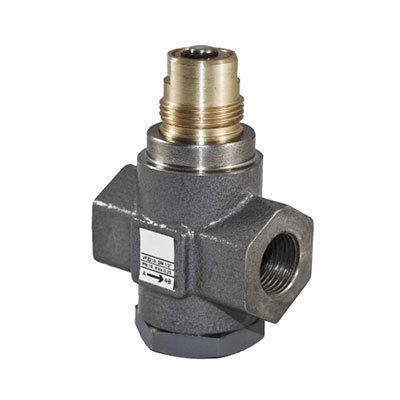
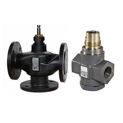
VFZ - flanged globe valves
Flanged globe valves series VFZ are used in HVAC systems to control fluid in heating, cooling, refrigeration and ventilation in residential or industrial buildings. Valves are fitted with female threaded connections in 2- and 3-way versions. 3-way valves must be used as mixing valves. They can also be used as diverting by reducing the max differential pressure value by 50%. Do not use the bypass (angle way) as a control port. VFZ valve bodies are motorized by SE4 series electric actuators. Make sure that pipes are clean, free from welding slags, that are perfectly lined up with the valve body and not subjected to vibrations when you start to mount the valve. The valve can be mounted vertically or horizontally, but never upside-down. While assembling, respect the flow directions indicated by the arrows located on the valve body. When the stem is up, the direct way is closed, with the stem down the direct way is open. The valve couldn’t be installed in an explosive atmosphere or in places in which temperature and humidity are outside ranges indicated in technical specifications.
Features
- Fluids type - water, water with glycol max. 50%
- Fluid temperature -10...120°C
- Leakage direct way A-AB perfect sealing
- Leakage angle way B-AB 0.2% of KVS value
| 2-way valve | 3-way valve | Connection | KVs [m3 /h] | Max. Differential pressure [bar] |
|---|---|---|---|---|
| VFZ210 | VFZ210 | G 1/2 | 0,25 | 2.5 (10,0) |
| VFZ211 | VFZ211 | G 1/2 | 0,4 | 2.5 (10,0) |
| VFZ212 | VFZ212 | G 1/2 | 0,63 | 2.5 (10,0) |
| VFZ213 | VFZ213 | G 1/2 | 1 | 2.5 (10,0) |
| VFZ214 | VFZ214 | G 1/2 | 1,6 | 2.5 (10,0) |
| VFZ215 | VFZ215 | G 1/2 | 2,5 | 2.5 (10,0) |
| VFZ216 | VFZ216 | G 1/2 | 4 | 2.5 (10,0) |
| VFZ218 | VFZ218 | G 3/4 | 4 | 2.5 (5,0) |
| VFZ220 | VFZ220 | G 3/4 | 6,3 | 2.5 (5,0) |
| VFZ225 | VFZ225 | G 1 | 10 | 2.5 (2,5) |
| VFZ232 | VFZ232 | G 1 1/4 | 16 | 2.5 (2,5) |
| VFZ240 | VFZ240 | G 1 1/2 | 18 | 2.5 (2,0) |
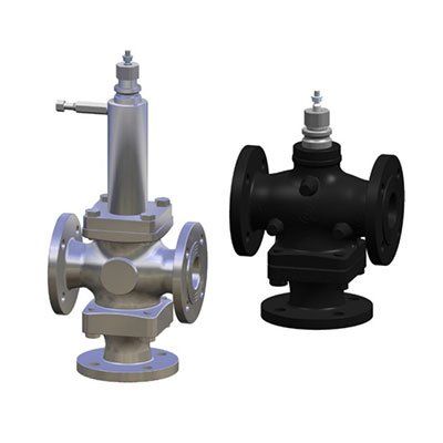
2 way single seat globe valves
Two-way single-seat globe valves are used to control fluids belonging to the group shown in the table according to article 9 of 97/23/CE directive (PED) in air-conditioning, thermos ventilation and heating plants and industrial processes; therefore, they cannot be employed as safety valves. They consist of a two-way simple seat valve body assembled with an electrical bidirectional actuator.
Technical specification remarks
- For applications with possible ice formation on stem and gasket (see 248 accessories).
- Graphite packing for high temperatures; forced lubrication on the extended neck. Teflon gasket for low temperatures, see (3).
- For applications on fluids from -10 to -20°C, replace the letter P with T, e.g., 2FAA50T. In such case, the max temperature is 230°C
- Double O-ring and graphite Teflon scraper ring.
- Group 1: water, overheated water, steam, diathermic oil.
*For different fluids belonging to these groups, please contact
| Model | 2FGB DN25÷150 | 2FGA DN15÷100 | 2FSA DN25÷65 | 2FAA DN15÷80 | 2FAAP DN15÷80 |
|---|---|---|---|---|---|
| Construction | PN16 | PN16 | PN25 | PN40 | PN40 |
| Body | cast iron | cast iron | spheroidal cast iron | steel | steel |
| Seat | cast iron | stainless steel | steel | stainless steel | stainless steel |
| Valve plug | forged brass | stainless steel | steel | stainless steel | stainless steel |
| Stem (diameter 9 mm) | stainless steel | stainless steel | stainless steel | stainless steel | stainless steel |
| Control characteristic | equal percentage | equal percentage | equal percentage | equal percentage | equal percentage |
| Stem sealing | Viton O-ring (4) | Teflon V-ring | Teflon V-ring | Teflon V-ring | -2 |
| Max. fluid temp. [°C] | 150 | 200 | 230 | 230 | 350 |
| Min. fluid temp. [°C] | 10(1) | 10(1) | 10(1) | 10(1) | -20 (1)(3) |
| Fluid, (5) | Group 2 | Group 2 | Group 2 | Group 2 | Group 1 |
| Connections | Flanges PN16 | Flanges PN16 | Flanges PN25 | Flanges PN40 | Flanges PN40 |
| Leakage % Kvs | 0,03 | 0,02 | 0,02 | 0,02 | 0,02 |
| Lowered stem action | normally open | normally closed | normally open | normally closed | normally closed |
3 way mixing globe valves
Two-way single-seat globe valves are used to control fluids belonging to the group shown in the table according to article 9 of 97/23/CE directive (PED) in air-conditioning, thermos ventilation and heating plants and industrial processes; therefore, they cannot be employed as safety valves. They consist of a two-way simple seat valve body assembled with an electrical bidirectional actuator.
Technical specification remarks
- For applications with possible ice formation on the stem and gasket, see 248 accessories.
- Graphite packing for high temperatures; forced lubrication on the extended neck. Teflon packing for low temperatures, see (4).
- Due to the bellow's presence, the max applicable pressure must not be higher than 5 bar.
- For applications on fluids from -10 to -20°C replace the letter P with the T, e.g., 3FAA50T. In such cases the max. temperature is 230°C
- Double O-ring and graphite Teflon scraper ring.
- Group 1: water, overheated water, steam, diathermic oil.
- For different fluids belonging to these groups, please contact us
- PN25 only for 3FAA125 and 3FAA125P.
- Leakage is measured according to the EN1349 standard.
| Model | 3FGB DN25÷150 | 3FSA DN25÷80 | 3FSAS DN25÷80 | 3FAA DN25÷125 | 3FAAP DN25÷125 |
|---|---|---|---|---|---|
| Construction | PN16 | PN25 | PN25(3) | PN40(7) | PN40(7) |
| Body | cast iron | spheroidal cast iron | spheroidal cast iron | steel | steel |
| Seat | cast iron | stainless steel | stainless steel | stainless steel | stainless steel |
| Valve plug | forged brass | stainless steel | stainless steel | stainless steel | stainless steel |
| Stem (diameter 9 mm) | stainless steel | stainless steel | stainless steel | stainless steel | stainless steel |
| Control characteristic | direct way = equal percentage angle way = linear | direct way = equal percentage (DN25÷65) linear (DN80) angle way = linear | direct way = equal percentage (DN25÷65) linear (DN80) angle way = linear | linear | linear |
| Stem sealing | EPDM O-rings (5) | Teflon V-ring | stainless steel bellows | Teflon V-ring | -2 |
| Max. fluid temp. [°C] | 150 | 230 | 300 | 230 | 350 |
| Min. fluid temp. [°C] | -10(1) | -10(1) | -10(1) | -10(1) | -20 (1)(4) |
| Fluid, (5) | Group 2 | Group 2 | Group 1 | Group 2 and 1 | Group 1 |
| Connections | Flanged PN16 | Flanged PN25 | Flanged PN25 | Flanged PN40 | Flanged PN40 |
| Leakage % Kvs | direct way 0,03, angle way 2 | 0,02 | 0,02 | 0,02 | 0,02 |